Why the viewport doesn't work in AutoCAD. AutoCAD viewports are an indispensable tool, the more you use, the more you like it
After creating a viewport, you can edit its properties. To do this, select the viewport whose properties will be changed and open the Properties dialog box by selecting the Properties command from the Format menu.
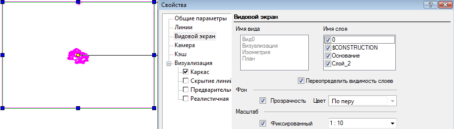
The Viewport page provides options for displaying the viewport and the objects it contains. Let's take a closer look at these options.
The View Name field contains a list of named views created for this drawing, and the view that fills the selected viewport will be highlighted.

To replace the current view with another, simply select its name from the list and click OK. The viewport content will change.


The Layer name field contains a list of all available layers in the drawing. You can choose which layers are displayed in a given viewport. In this case, the display of layers for the drawing itself will remain unchanged.

By default, the Override layer visibility option is enabled, which allows you to determine which layers will be displayed in the viewport, regardless of whether they are visible in the drawing or not. If this option is disabled, the visibility of layers will be subject to the general settings of the drawing. Disable one of the drawing layers by calling the Layers dialog box from the Settings / Layers menu.

In the viewport, the disabled layer is still visible. Open the Viewport Properties dialog box and turn off the Override layer visibility option, leaving all layers visible.

Close the Properties dialog box by clicking OK. The disabled layer is now invisible in the viewport.
You can set a background for the viewport. To do this, you need to turn off Transparency and select Background Color from the color palette.

The Scale parameter allows you to set the scale factor for the viewport image, while the size of the viewport itself remains unchanged.
Remember that dimensions included in a viewport are associative with the viewport, so if you change the viewport scale, the scale of the dimensions will also change.
To disable the visible outline of the viewport, you must disable the Visible Frame option, which is enabled by default.

Disabling the viewport outline can make it difficult to select, in which case you can use the F6 and F7 keys. Disabling the Viewport Enabled option allows you to hide the contents of the viewport. Only the outline will remain visible if the Visible frame option is enabled.

If you need to make small changes to a drawing while in paper space, it is convenient to use the Model Space (Floating) command from the Workspace menu. This will allow you to use model space tools inside the viewport.

Having selected the viewport, call the Model Space (Floating) command. The viewport outline is outlined with a thick line, and the model space tools become available.

We will make the necessary changes. Please note that if you rotate a view, it will not return to its original position after you finish editing. To exit this mode, simply click the mouse anywhere in the drawing outside the edited viewport.

You can not only change the properties of the viewport or edit its contents, but also change the shape of the outline. This may be necessary when viewports partially overlap each other. You can select any closed 2D object as a new contour. Let's create such an object.

From the Workspace menu, select the Refresh Viewport Border command.

Select the viewport whose outline we want to change, and then select the 2D object. The viewport outline has changed.

If necessary, you can edit the scale in Viewport Properties.

Hello my dear friend!
In this video we will figure out how to create a viewport, how to change it, rotate it, and set the scale.
From the video you will learn:
– How to add a viewport to AutoCAD
– How to change the viewport
– How to configure viewports on a sheet in AutoCAD
– How to set the viewport scale
– How to remove the viewport frame in AutoCAD
Video version of the lesson:
Text version of the lesson:
Greetings! Today we will learn about how to create and use Viewports in AutoCAD.
Follow step by step instructions and you will definitely succeed!
Step 1. You should start with the fact that by default, when you go to the “sheets” tab, there is an already created viewport in AutoCAD. In our case (see screenshot below) we have already added a frame.
Step 2. An existing viewport can be deleted or resized. To do this, you need to select the outer frame and use the blue handles to change the size to the desired size. If you want to delete it, select the frame and press the DELETE button.

Step 3. Now, let's learn how to add new ones viewports on . To do this, go to the SHEET tab and select RECTANGULAR viewport.

Step 4. Now, we need to define two opposite points to create a rectangular viewport.

When you do this, you will end up with a rectangular viewport (see screenshot below).

Step 5. In addition to a rectangular viewport, you can also specify a polygonal one. To do this, select “ POLYGONAL“.

Step 5.1. Using the “Polygonal” command we create borders new viewport.

By creating the outline, we will get a new viewport as shown below.

Step 6 For editing viewport, you need to select the outer frame and mix the blue handle or handles (if you select two of them at once on one side of the rectangle). This way you change the size of the screen itself.

The result of resizing the viewport using grips. The main thing to remember is that to change the size you only need to select the outer frame and pull the blue handle in the desired direction. If you select two handles at once, the size will change slightly differently. I recommend practicing.

Step 7 Now let's learn how to turn viewport. This is done very simply. To do this, simply select the outer contour of the frame, right-click and select “rotate” from the list. Then, by selecting a base point (for example, one of the four points of the viewport frame), we rotate the screen relative to the selected point. (see screenshots below).

Rotation result viewport relative to the base point. The frame can be rotated to any angle.

Step 8 Let's learn how to set the viewport scale. Before this, you need to activate it; to do this, you need to left-click inside the frame itself twice. If the outline of the frame becomes blacker and thicker, then everything was done correctly. (see screenshot below).

Step 8.1. In activation mode viewport, we can move around the model space. This way we can find the drawing we need. Now we will simply center the drawing and set the scale of this very view. Our goal is to fit the entire drawing that we selected in activation mode into given size viewport. To do this, click on the scale tab and set M 1:50 for example.

Interval. As we see, this is not enough. Change to scale 1:100.

Result. As you can see, by choosing a scale of 1:100 we will insert our drawing into the viewport frame. Now you can center it. To do this, hold down the mouse wheel (click on it) and a hand will appear. With the help of our hands we can make adjustments and place the drawing as we need. (see screenshots).

For decontamination viewport just double-click with the left mouse button outside the frame, anywhere.

Step 9 All we have to do is find out how to prevent the viewport frame from printing. Those. make sure that when printing a drawing, the outline of the viewport frame itself is not displayed on a sheet of paper, yes, this also happens and it is very unpleasant when, along with your work, you print the frame itself. So now let's learn this too. And it's very easy to do!
So, let's highlight our frames.

Then, go to the “HOME” tab, we are interested in the “LAYERS” block. In this block, we need to select the layer that has the “Do not print” option. By default, AutoCAD always has such a layer, it is called defpoints. Therefore, if you have one in the list of layers, just select it. Thus your viewport will be assigned to the “defpoints” layer and will not print. But if you don’t have such a layer, it doesn’t matter, below we will learn how to create a layer for viewports with the “do not print” option.

Step 9.1. To create a “viewport” layer, click on the “layer properties” button on the “layers” block. This will open a new window where you can create a layer and set it to “do not print.”

Create a layer and give it the “do not print” property, the crossed out printer icon. When you do it and transfer it view frame on this layer, it will not be printed. In our case, the viewport or VE layer has already been created and has the “do not print” option. (see screenshot below)

This lesson will describe ways to view drawings as well as views and viewports. When creating a drawing, it often happens that the displayed working field is not enough to place all the elements, and in order for the scale of the drawing to remain the same, a drawing viewing system is used. And the use of views and viewports is extremely necessary when creating 3D models, in cases where it is necessary to change the displayed projection views, as well as when viewing a three-dimensional model.
View drawings
IN AutoCAD system drawings are created using actual sizes objects. Detailed viewing of any drawing elements is carried out using a series of commands ZOOM (zoom), PAN (panning), VIEV (view).
Changing the drawing scale
Zooming (ZOOM)
Command entry methods:
- Type the command on the keyboard: ZOOM
- Call from the menu: View>Zoom
- Buttons on viewport
After entering the command, the system prompts you to select one of the options:
- Realtime mode for dynamically zooming in or out of the drawing view relative to its center on the screen. To zoom in on a drawing, hold down the LMB and drag the cursor up, and to zoom out of the drawing, hold down the LMB and drag the cursor down.
- Previous – canceling zoom steps. Selecting the option cancels the last zoom command and returns to the previous view of the drawing.
- Window This zooming method allows you to select on the screen a part of the drawing that needs to be examined in more detail. A rectangular frame is defined by points that are the vertices of the opposite vertices of the rectangle. To set it, move the cursor over the required point in the work area and click LMB. Then drag the cursor to the opposite point of the area. The entire area you selected will be enlarged to its maximum size.
- Dynamic – Dynamic When using this option, the view of the drawing moves away as much as possible and the cursor takes on the appearance of a rectangle with a cross inside. Everything that falls within the rectangle will be zoomed in for viewing. To change the size of the rectangle, click LMB and drag the cursor to the right to enlarge the rectangle or to the left to reduce it. After this, move the rectangle over the area you want to enlarge and press the Enter key.
- Scale – The option is used both to zoom in and out of the drawing. The drawing scale value is entered in command line as a whole or as a fractional number, or a number is written down that shows how many times to change the scale of the drawing - 2x, 3x, 0.5x.
- Center – The option allows you to center the image relative to a specified point and set the zoom factor.
- Object – Enlarges one or more selected objects to fill the entire screen.
- In – Each time you press, the drawing is doubled in size.
- Out – Each time you press, the drawing moves twice as far away.
- All– the option is used to zoom out the drawing as much as possible and shows the entire worksheet for creating drawings. The method is quite convenient for viewing very large drawings. But the drawings are so far away that small details are difficult to distinguish.
- Extents– This method of zooming places all objects that are drawn in the drawing within the working area. At the same time, it stretches them to their maximum width or height.
Move a drawing
Panning (PAN)
Command entry methods:
- Type the command from the keyboard: PAN
- Call from menu View>Pan
- Button on viewport
The pan command is used to move a drawing without changing its size. This allows you to revisit previously hidden parts of the drawing.
Views and viewports.
To conveniently and quickly change the viewport in new versions of AutoCAD, use view panel. In which, using the module Gizmo Box the user can choose one of the standard projection and axonometric views, or set his own view.
Controlling Visibility in Layout Viewports
Freeze Layers in Layout Viewports
An advantage of using sheet viewports is the ability to selectively freeze different layers in any one of the viewports. Visibility settings for new viewports and for new layers can be set by default. As a result, you can view different objects in each of the sheet viewports.
You can freeze or unfreeze layers in the current or subsequent viewport without changing the visibility of layers in other viewports. Frozen layers are invisible, and objects on frozen layers are not displayed, printed, or regenerated. The drawing shows the result of freezing a landscape layer in one of the viewports.
When defrosted, the visibility of the layer is restored. The easiest way to freeze and unfreeze layers in the current viewport is in the Layer Properties Manager.
On the right side of the Layer Properties Manager, select or clear the Frozen on VE check box to freeze one or more layers in the current layout viewport. To display the Frozen on VE column, you must be on the Sheet tab. Make the sheet viewport active by double-clicking on it.
Automatically freeze and thaw layers in new viewports
When you create new sheet viewports, you can automatically freeze specific layers in them. For example, you can hide dimensions by freezing the DIMENSIONS layer for all new viewports. If dimensions must be present on one of the viewports, then the frozen state can be overridden for that viewport. Turning layer freeze on or off for new viewports does not change the visibility of layers in existing viewports.
Create new layers frozen in all viewports
You can create layers that will be frozen in all existing and newly created layout viewports. These layers can later be unfrozen in specific viewports. This way you can quickly create a new layer that should only be visible in one viewport.
Freeze or unfreeze layers in the current layout viewport
1. Double-click on the sheet viewport to set it as the current sheet.
3. In the Layer Properties Manager window, select the layers that need to be frozen or unfrozen.
4. Click the icon in the VE Frozen column for one of the selected layers.
5. Click OK.
LAYER
View a list of layers frozen on the current screen
2. Double-click on the sheet viewport to set it as the current sheet.
4. In the VE Frozen column of the Layer Properties Manager, look at the icon indicating the frozen/thawed state of the layer in the current viewport.
5. Click OK.
LAYER, LAYER
Freeze or unfreeze layers in all viewports
1. Go to the sheet layout tab.
2. Select the "Format"? "Layer" menu.
3. In the Layer Properties Manager window, select one or more layers that need to be frozen or unfrozen.
To select multiple layers, hold down the CTRL key. To select multiple layers one after another in the list, hold down the SHIFT key.
4. In the Freeze column, click on the Freeze/Thaw icon.
LAYER
Freeze or unfreeze layers in paper space
1. Go to the sheet layout tab.
2. Check that the paper space is active (the status bar should be labeled "SHEET").
3. Select the "Format" menu? "Layer".
4. In the Layer Properties Manager window, select the layers that need to be frozen or unfrozen.
5. In the Freeze column, click the icon to freeze or thaw the layer. The sun icon means the layer is unfrozen; icon with a snowflake - the layer is frozen.
6. Click "OK".
LAYER
Freeze or unfreeze layers in new viewports
1. Go to the sheet layout tab.
2. Select the "Format"? "Layer" menu.
3. In the Layer Properties Manager window, select the layers that you want to freeze or unfreeze in new viewports.
To select multiple layers, hold down the CTRL key. To select multiple layers one after another in the list, hold down the SHIFT key.
4. In the "Frozen on new EVs" column, click the icon to change the layer state. The sun icon means the layer is unfrozen; icon with a snowflake - the layer is frozen.
5. Click "OK".
LAYER
Create new layers frozen in all viewports
1. Go to the sheet layout tab.
2. Select the "Format"? "Layer" menu.
3. Click the "New" button and create a layer.
4. Enter a new name for the layer.
5. In the Freeze column, click the icon to change the layer's state to frozen. The sun icon means the layer is unfrozen; icon with a snowflake - the layer is frozen.
6. Click "OK".
LAYER, LAYER
Quick reference
Teams
LAYER
Managing layers and their properties
LAYER
Control layer visibility for individual viewports
System Variables
No records
Utilities
No records
Keywords for teams
No records
Change the light intensity of objects in worksheet viewports
Intensity controls the amount of ink used to print an object. This allows objects to be represented on screen and on paper in different shades of gray without changing their color properties.
To assign an intensity value to an object, you must assign it a print type and then an output intensity value for that style.
The intensity value ranges from 0 to 100. The default value is 100, which is full intensity. An intensity value of 0 corresponds to a white output.
See also:
Setting options for printing objects
Set the display intensity of objects in a sheet viewport
1. Select the "File" menu? "Print Style Manager".
2. Right-click on the CTB or STB file. Click "Open".
3. On the "Card" tab of the Print Style Table Editor, select a style to edit.
4. In the "Intensity" parameter field, enter a value from 1 to 100.
5. Click the "Accept" button.
6. On the sheet, select the "File" menu? "Sheet Options".
7. In the Sheet Settings Manager dialog box, click the Edit button. In the Sheet Options dialog box that opens, select the edited plot style from the Plot Style Table list.
8. Double-click the mouse button on the sheet viewport containing the objects whose intensity you want to change.
9. Select the objects whose print style you want to change.
10. Right-click in the drawing area and select “Properties” from the context menu.
11. In the “Properties” palette, use one of the following techniques:
When using named plot style tables, set the Plot Style property to the edited plot style. If this print style is not in the list, select "Other" and set the current table to the table that contains the previously edited print style. In the Select Plot Style dialog box, select the desired plot style from the Plot Styles list.
When using color-dependent plot style tables, set the "Color" property to the color for which the plot style was edited.
Quick reference
Teams
PARAMLIST
OKNOSV
System Variables
No records
Utilities
No records
Keywords for commands
No records
Turn worksheet viewports on or off
Disabling some worksheet viewports or limiting the number of active viewports can save time.
A large number of active viewports can slow down the system because significant time is spent regenerating images. Disabling some worksheet viewports or limiting the number of active viewports can save time. The following illustration shows the result of disabling two viewports.
Newly created viewports are enabled by default. By turning off the visibility of those not used in this moment viewports, you can move and resize viewports without wasting time waiting for regeneration to complete.
In addition, the viewport can be disabled if it is not intended to be plotted on the plotter.
Turn viewports on or off using the Properties panel
1. Go to the "Sheet" tab in paper space.
2. Select the viewport border you want to turn on or off.
3. Right-click and select context menu"Properties".
4. On the Properties palette, in the Miscellaneous group, select the On property and set it to Yes or No.
To change the properties of a non-rectangular viewport, in the Properties palette, first select Viewport (1) from the list that displays All (2).
Standard
PROPERTIES
Select the viewport and right-click in the drawing area.
Select "Visibility of objects on VScreens" in the context menu.
Quick reference
Teams
SVID
Create and manage viewports in sheets
PARAMLIST
Control layout options, print device, paper size, and other settings for each new sheet
OKNOSV
Managing object properties
VECRAN
Creates multiple viewports in model space and paper space.
System Variables
MAHASTVP
Sets the maximum number of viewports that can be active at the same time
Utilities
No records
Keywords for commands
No records
There are several ways to control the visibility of objects in a viewport. They can be used to reduce the number of screen updates and to highlight or hide various elements of a drawing.
AutoCAD users are accustomed to the viewport shape being a rectangle. There is a great opportunity to make the shape of the viewport arbitrary.
For example, let's make a remote element that will show the welded joint in the drawing on an enlarged scale.
To do this, use the command _vports We create a regular rectangular viewport, adjust it to the desired position of the model, set the scale and lock it.


In the first case, we draw some object in paper space above the viewport, such as a circle. We select it as an object for cropping, as a result of which the viewport automatically acquires boundaries corresponding to the contour of the circle.


If we select a polygonal viewport border, we can actually construct it not only from a polyline, but also from circular arcs. This way you can get a beautiful curved border of the extension view, which can be edited using the “handles” like a polyline. Choose what you like best. Of course, the method with a secant circle is much faster :)


In most cases, the border of the image of the extension element according to the ESKD should not be closed. The outline of a curved viewport can be trimmed with the command _trim along secant lines drawn in appropriate places on top of the viewport.

The compromise between compliance with design standards, convenience and speed of work is up to you.
I wish everyone correct and beautiful drawings!