What is an oblique bridge? Welding inverter - asymmetrical (oblique bridge) with microcontroller control
A welding inverter is a fairly popular device that is necessary both in the household and in an industrial enterprise. This is not surprising, because the power sources that were used before (converters, transformers, rectifiers) had many disadvantages. Among them are weight and dimensions, high energy consumption, but a small range of control of the welding mode and low frequency transformations. By making a welding inverter using thyristors with your own hands, you will receive a powerful power supply for the necessary work. This will also help you save a lot of money, although it will still require certain labor and material costs.
Welding inverter: features and functions of the device
The inverter's job is to convert alternating mains current into its direct high-frequency counterpart.
This happens in several stages. To the rectifier block from network is coming current. There, after transformation, the voltage changes from alternating to constant. And the inverter performs a reverse conversion, that is, the incoming DC voltage again becomes alternating, but at a higher frequency. After this, the voltage is reduced by a transformer, and this parameter is modified into a high-frequency DC voltage through the output rectifier.
The design of the welding inverter and its features
Due to the fact that there are no heavy parts in the design of the device, it is very compact and lightweight. It includes the following components:

The design of a simple cross-coupled inverter.
- inverter;
- network and output rectifiers;
- throttle;
- high frequency transformer.
Even novice welders can work with such machines. They are used both in everyday life and in the construction industry or in car services. Due to the fact that there is adjustment of operating modes, you can cook both thin and thick metals. And the increased conditions of arc combustion and weld formation give you the opportunity to weld any alloys, ferrous and non-ferrous metals using welding inverters, using all possible welding technologies.
Benefits of using an inverter
In the field of welding equipment, such devices are in particular demand due to their many advantages and advantages. By making an inverter with your own hands, you will receive:

- the ability to weld complex non-ferrous metals and structural steels;
- protection against overheating, mains voltage fluctuations, and current overloads;
- high stability of the welding current even though the voltage may fluctuate in the network;
- high-quality seam;
- There will be virtually no spatter during welding;
- arc burning will be stabilized in a given key, even if external adverse influence is observed;
- many other useful functions.
DIY inverter circuits
Taking as a basis how the circuit is built and how the inverter conversion process itself is controlled, there are several types of devices that are the most common in use. The full bridge and half bridge options refer to two push-pull circuits, and the “oblique” bridge refers to a single-stroke circuit. A full bridge circuit, called push-pull, operates with bipolar pulses. They are fed to key transistors (which are paired), and they lock and open the electrical circuit.

Slant bridge inverter circuit.
The half-bridge circuit will differ from the previous version in that its current consumption is increased. Transistors operating on the same push-pull model act as keys. Each of them is supplied with half of the input mains voltage. The power of the inverter, in comparison with the current of a full bridge, is half the value. This scheme has its advantages in low-power devices. In addition, you can use a group of transistors, rather than one very powerful one.
The last option is an “oblique” bridge. These are inverters that operate on a single-cycle principle. Here you will be dealing with unipolar impulses. Simultaneous opening of the transistor switches will eliminate the possibility of a short circuit. But among the disadvantages of this scheme is the magnetization of the transformer magnetic circuit.
Look at one of the standard inverter circuits. This is a design designed by Yu. Negulyaev. To assemble such a device at home, you will need your desire, readiness to work and the necessary element base, which you can either find on the radio market or remove from old household appliances.
Instructions for assembling the device

Standard inverter circuit designed by Yu. Negulyaev
Take a 6mm duralumin plate. Connect all heat-emitting conductors and wires to it. Please note that here the wire does not need to be surrounded with thermal insulating material. Using old scheme(for example, a computer), you do not have to look for transistors and thyristors separately.
Next, prepare a special high-power fan (you can even use a car radiator). It will blow air over everything, including the resonant choke. Be sure to press the latter onto your base using a spacer seal.
To make the throttle device itself, take six copper cores. You can find them on the market or make them yourself from parts of an unnecessary old TV. Press the diodes to the base of the circuit, and then attach voltage regulators and insulation seals to them.
When installing the transformer, insulate the conductor bundles using electrical tape or fluoroplastic strip. Place the conductors in different directions so that they do not come into contact and cause malfunctions. You will need to install a force field on the field-effect transistor to extend the performance of your inverter. To do this, take a copper wire with a 2 mm cross-section. Having tinned it, wrap it in several layers with regular thread. This way you will protect your conductor from various damages both during soldering and welding. To secure the installation, use insulating heels. This way you will also transfer the load from the transistors to them.
Installations for automatic welding of longitudinal seams of shells - in stock!
High performance, convenience, ease of operation and reliability in operation.
Welding screens and protective curtains - in stock!
Radiation protection when welding and cutting. Big choice.
Delivery throughout Russia!
Most often, when constructing welding inverters, three main types of high-frequency converters are used: half-bridge, asymmetric bridge (or “oblique bridge”) and full bridge. Under the guise of a half bridge and a full bridge, there are resonant converters. Depending on the control system for the output parameters, converters are available with PWM (pulse width), with PFM (frequency control), with phase control, and combinations of these three. All these types of converters have their advantages and disadvantages. Let's start with a half bridge with PWM. The block diagram of such a converter is shown in Fig. 3.
This is the simplest converter of the two-stroke family, but no less reliable. The disadvantage of this circuit is that the voltage “swing” on the primary winding of the power transformer is equal to half the supply voltage. But on the other hand, this fact is a plus; you can use a smaller core without fear of entering saturation mode.
For low-power inverters (2-ZkW), such a converter is very promising. But PWM control requires special care when installing power circuits; drivers must be installed to control power transistors. Transistors of such a half-bridge operate in hard switching mode, so increased demands are placed on control signals.
There must be a “dead time” between two antiphase pulses, the absence of a pause, or its insufficient duration, always leads to the occurrence of a through current through the power transistors.
The consequences are easily predictable - failure of transistors. A very promising type of half-bridge converter is the resonant half-bridge. The block diagram of such a half-bridge is shown in Fig. 4.

The current flowing through the power circuits has a sinusoidal shape, and this removes the load from the filter capacitors.
With this design, power switches do not require drivers! An ordinary pulse transformer is enough to switch the power transistors. The quality of control pulses is not as significant as in a PWM circuit, although there should be a pause (“dead time”).
Another plus is that this scheme allows you to do without current protection and the shape of the current-voltage characteristic (volt-ampere characteristic) has an immediately falling form and does not require parametric shaping.
The output current is limited only by the magnetizing inductance of the transformer and can reach significant values during a short circuit; this must be taken into account when choosing output diodes, but this property has a positive effect on the ignition and burning of the arc!
Typically, the output parameters are regulated by changing the frequency, but the use of phase control gives much more advantages and is the most promising for a welding inverter, since it allows you to bypass such an unpleasant phenomenon as the coincidence of resonance with the short-circuit mode, and the range of adjustment of the output parameters is much wider. Phase adjustment allows you to change the output current practically from 0 to Imax.
The next scheme is an asymmetric bridge, or “oblique bridge”. The block diagram of such a converter is shown in Fig. 5.
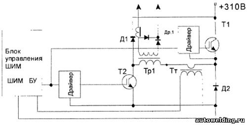
The asymmetric bridge is a single-cycle, forward-flow converter.
A converter of this configuration is very popular both among manufacturers of welding inverters and among radio amateurs. The first welding inverters were built exactly like an “oblique bridge”. Simplicity and reliability, ample opportunities for adjusting the output current, noise immunity - all this still attracts developers of welding inverters.
And although the disadvantages of such a converter are quite significant, these are large currents through transistors, high requirements for the shape of control pulses, which implies the use of powerful drivers to control power switches, high requirements for the installation of power circuits, large pulse currents place high demands on input filter capacitors, electrolytic Capacitors really don't like large pulse currents. To keep transistors in the ODZ (permissible value range), RCD chains (snubbers) are required.
But, despite all these shortcomings and low efficiency, the “oblique bridge” is still used in welding inverters to this day. Transistors T1 and T2 operate in phase, opening together and closing together. The energy is not stored in the transformer, but in the output inductor of the inductor. The duty cycle does not exceed 50%, which is why to obtain the same power with a bridge converter, double current through the transistors is required. The operation of such a converter will be examined in more detail using the example of a real welding inverter.
The next type of converter is a full bridge with PWM. Classic push-pull converter! The block diagram of the full bridge is shown in Fig. 6.

The bridge circuit makes it possible to obtain power 2 times more than a half-bridge, and 2 times more than an “oblique bridge”, with the same values of currents and switching losses. This is explained by the fact that the “swing” of the voltage of the primary winding of the power transformer is equal to the supply voltage.
Accordingly, to obtain the same power, for example, with a half-bridge (in which the drive voltage is 0.5U supply), the current through the transistors will be 2 times less! Full bridge transistors operate diagonally when T1 - T3 are open, T2 - T4 are closed, and vice versa. The current transformer monitors the amplitude value of the current flowing through the switched on diagonal. You can regulate the output current of such a converter in two ways:
1) change the duration of the control pulse, leaving the cutoff voltage unchanged;
2) change the level of the cutoff voltage coming from the current transformer, leaving the duration of the control pulses unchanged.
Both of these methods allow you to change the output current within a fairly wide range. The disadvantages and requirements of a full bridge with PWM are exactly the same as those of a half bridge with PWM. (See above). And finally, let's consider the most promising RF converter circuit for a welding inverter - a resonant bridge. The block diagram is shown in Fig. 7.

As it may seem at first glance, the resonant bridge circuit is not very different from a PWM bridge, and this is true. In practice, only an LC resonant circuit is additionally introduced, connected in series with the power transformer. However, the introduction of this chain completely changes the processes of power transfer. Losses are reduced, efficiency increases, the level of electromagnetic interference is reduced by orders of magnitude, and the load on the input electrolytes is reduced. As you can see, you can completely remove current protection; power transistor drivers may only be needed if MOSFET transistors with a gate capacitance greater than 5000pF are used. For IGBT transistors, one pulse transformer is sufficient.
The output current of the resonant converter can be controlled in two ways: frequency and phase. Both of them were mentioned earlier, in the description of the resonant half-bridge. And the last type of RF converter is a full bridge with a leakage choke. Its circuit is practically no different from the circuit of a resonant bridge (half-bridge), just like the LC circuit is connected in series with a transformer, only it is not resonant. C = 22 µFx63V works as a balancing capacitor, and L of the inductor acts as a reactance, the value of which linearly depends on the frequency. The control of such a converter is frequency. As the frequency increases, the resistance L increases. The current through the power transformer decreases. Simple and reliable. Most industrial inverters are built on this principle of adjusting and limiting the output current.
Schematic of the power section with power supply and drivers.
……….
The welding inverter shown in the diagram is built according to the single-cycle forward flow diagram. Unipolar pulses of rectified mains voltage with a filling of no more than 42% are supplied to the primary winding of the welding transformer using two switches. The magnetic core of the transformer experiences one-sided magnetization. During pauses between pulses, the magnetic circuit is demagnetized in a so-called private loop. The demagnetizing current, thanks to the reverse-connected diodes, returns the magnetic energy stored in the transformer core back to the source, recharging the capacitors (2 x 1000 µF x 400 V) of the drive.
……….
In direct operation, energy is transferred to the load through a welding transformer and directly connected rectifier diodes (2x150EBU04). During the pause between pulses, the current in the load is maintained thanks to the energy accumulated in the inductor. In this case, the electrical circuit is closed through freewheeling diodes (2x150EBU04). It is well known that these diodes have a greater load than straight diodes. The reason is that the current in a pause flows longer than in a pulse.
……….
A 1200 uF x 250 V capacitor connected to the welding wires through a 4.3 Ohm resistor ensures accurate ignition of the arc. Perhaps this is one of the successful circuit solutions for ignition in space.
……….
The oblique bridge keys operate in hard switching mode. Moreover, the switching mode is obviously facilitated by the always present leakage inductance of the welding transformer. And, since by the time the switches are turned on, it is assumed that the magnetic circuit of the transformer is completely demagnetized, then due to the lack of current in the primary winding, turn-on losses can be neglected. The shutdown loss is very significant. To reduce them, RCD snubbers are installed parallel to each key.
……….
To ensure smooth operation of the keys, in the moments between switching on, negative voltage is applied to their gates thanks to a special driver switching circuit. Each driver is powered from a galvanically isolated source (about 25 V) power supply. The supply voltage of the “upper” driver is used to turn on relay K1, the contacts of which bypass the starting resistor.
……….
The power supply (classic low-power flyback) has 3 galvanically isolated outputs. If the parts are in good condition, it starts working immediately. The voltage for drivers is 23-25V. Voltage 12 V is used to power the control unit.
……….
Significant heat sinks must be provided for the input rectifier, switches and output rectifier. The operating time of the device will depend on the size of these radiators and the intensity of their blowing. Since the device provides a significant welding current (up to 180 A), the keys must be soldered to copper plates 4 mm thick, then these “sandwiches” must be screwed to the radiators through thermally conductive paste. It is written about how to do this. When attaching the keys, the radiator seat should be perfectly flat without chips or cavities. It is desirable that at the place where the keys are attached the radiator has a solid body with a thickness of at least 10 mm. As practice has shown, for better heat removal there is no need to insulate the radiator keys. It is better to isolate the radiator from the device body. The blower also needs to be supplied with a transformer, a choke and, of course, all resistors with a power of 25 and 30 W. The remaining elements of the circuit do not require radiators or airflow.
Control block

Diagram of the control unit for a full-bridge welding inverter
……….
The control unit is built on the basis of the common TL494 PWM controller using one regulation channel. This channel stabilizes the current in the arc. The current setting is generated by the microcontroller using the CCP1 module in PWM mode at a frequency of approximately 75 kHz. The PWM filling will determine the voltage across capacitor C1. The magnitude of this voltage determines the magnitude of the welding current.
……….
The microcontroller also blocks the inverter. If a high logic level is applied to the DT(4) input of the TL494, the pulses at the Out output will disappear and the inverter will stop. The appearance of a logical zero at the RA4 output of the microcontroller will lead to a smooth start of the inverter, that is, to a gradual increase in the filling of pulses at the Out output to the maximum. Inverter blocking is used at the moment of switching on and when the temperature of the radiators is exceeded.
This is what happened in hardware. Power supplies, drivers and control unit on one board. 
.
In my device, the indicator and keyboard are connected to the control unit via a computer cable. The loop passes in close proximity to the radiators of the keys and the transformer. In its pure form, such a design led to false pressing of the keys. I had to use the following special ones. measures. The cable has a ferrite ring K28x16x9. The train is twisted (as far as its length allows). For the keyboard and thermostats, additional 1.8K pull-up resistors were used, shunted by 100 pF ceramic capacitors. This circuit design ensured that the keyboard was noise-resistant and false key presses were completely eliminated.
……….
Although, my opinion is that interference should be prevented into the control unit. To do this, the control unit must be separated from the power part by a solid metal sheet.
Inverter setup
……….
The power section is still de-energized. We connect the previously tested power supply to the control unit and plug it into the network. All eights on the indicator will light up, then the relay will turn on and, if the thermostat contacts are closed, the indicator will show a current setting of 20 A. Using an oscilloscope, we check the voltage at the gates of the keys. There should be rectangular pulses with fronts of no more than 200 ns, a frequency of 40-50 kHz, a voltage of 13-15 V in the positive region and 10 V in the negative. Moreover, in the negative region the pulse should be noticeably longer.
……….
If everything is so, we assemble the entire inverter circuit and connect it to the network. The display will first display eights, then the relay should turn on and the indicator will show 20 A. By clicking the buttons, we try to change the current setting. Changing the current setting should proportionally change the voltage on capacitor C1. If, after changing the current setting, you do not press the buttons for more than 1 minute, the task will be recorded in non-volatile memory. The message “RESERVE” will appear briefly on the indicator. The next time the inverter is turned on, the current command value will be equal to the value that was recorded.
……….
If everything is so, we set the task to 20 A and connect a load rheostat with a resistance of 0.5 Ohm to the welding wires. The rheostat must withstand the flow of a current of at least 60 A. We connect a voltmeter of the magnetoelectric system with a scale of 75 mV to the shunt terminals, for example the Ts 4380 device. On a loaded inverter we try change the current setting, and use the voltmeter readings to control the current. In this mode, the rheostat can make a sound resembling a ringing. There is no need to be afraid of it - current limitation works. The current must vary proportionally to the reference. We set the current setting to 50 A. If the voltmeter readings do not correspond to 50 A, then with the inverter turned off, we solder in resistance R1 of a different value. By selecting resistance R1, we ensure that the current setting corresponds to the measured one.
……….
We check the operation of thermal protection. To do this, we break the thermostat circuit. The indicator will display “EroC”. The pulses on the key gates should disappear. We restore the thermostat circuit. The indicator should show the set current. Pulses should appear on the key gates. Their duration should gradually increase to maximum.
……….
If everything is so, you can try to weld. After 2-3 minutes of welding with a current of 120-150 A, turn off the inverter from the network and look for the 2 hottest radiators. They need to install protective thermostats. If possible, thermostats are installed outside the blowing area. 
The arc welding machine must provide a decreasing current-voltage characteristic in the load (arc). In bridge inverters, as a rule, the falling characteristic is provided by rather complex electronics with mandatory feedback by current. From the point of view of ease of control, in my opinion, the resonant bridge is the most attractive. In it, the falling characteristic of the welding current source is ensured by the parametric properties of the resonant circuit in the primary circuit of the inverter.
A feature of the inverter presented in this article is not only the use of a full resonant bridge, but also its control using a PIC16F628-20I/P microcontroller.
Let us immediately note that the maximum welding current of the inverter depends on the setting. Its value is entirely determined by the width of the non-magnetic gap in the magnetic circuit of the resonant choke. For the power elements used in the inverter, subject to their thermal conditions, the welding current can reach 200 A.
The inverter circuit diagram is divided into two parts. On Fig.1 the power section is shown, and Fig.2— diagram of the power supply with the control unit. A classic bridge welding inverter consists of a mains voltage rectifier with filter capacitors. A direct voltage of 300 V is converted using 4 switches into an alternating voltage of a higher frequency, which is lowered and then rectified using a welding transformer.
Power part
In resonant converters, a resonant inductor L1 and a resonant capacitor C1-C10 are connected in series with the primary winding of the welding transformer T1 (see Fig. Fig.1 on which the power circuits are highlighted with bold lines). The inductance of the series circuit consists of the inductance of the resonant choke L1 and the inductance of the primary winding of the transformer T1. The secondary winding T1 is loaded with a welding arc. If the capacitance C1-C10 and inductance L1 are constant values, then the inductance of the primary winding T1 depends on the load resistance in the secondary winding, i.e. from welding current. The maximum inductance of the primary winding T1 corresponds to the “no-load” mode of the inverter, and the minimum inductance corresponds to the short-circuit mode. The load resistance also determines the quality factor of the circuit. Thus, the resonant frequency of the circuit is minimal in the “no-load” mode (with maximum inductance of the primary winding T1) and maximum in short-circuit mode (with minimal inductance of the primary winding T1). When the inverter load is a welding arc, the resonant frequency of the circuit depends on the current in the arc.
From all that has been said above, it is obvious that the frequency of the inverter when operating at maximum power in the arc should be lower than the natural frequency of the resonant circuit of the inverter in short-circuit mode and higher than it in the “idle” mode. It is optimal that the resonance occurs at the natural frequency of the circuit, at which the arc develops maximum power(f MAX. POWER). This is precisely the main criterion correct settings inverter If in this case the inverter frequency is increased relative to f MAX. POWER , the arc current decreases due to an increase in the inductive reactance of the resonant inductor L1. This is how frequency regulation of the current in the welding arc is carried out.
Resonance in the inverter circuit during short circuit and incorrect setting inverter is also possible at a frequency higher than f MAX. POWER .
Note also that resonance is unacceptable in short-circuit mode for transistor switches of the inverter due to the occurrence of overcurrent in the primary circuit. Since short circuit mode is the normal mode for the welding machine, it is necessary to prevent the inverter from operating at frequencies above f MAX. POWER in case of a short circuit in the welding circuit.
To do this, the microcontroller in this inverter continuously monitors the fact of a short circuit in the welding wires using a special detector. When a short circuit occurs, the microcontroller automatically reduces the inverter frequency to the previous set value f MAX. POWER - at this frequency, resonance in a short circuit is impossible, which prevents excessive current from flowing in the primary circuit and, accordingly, through the switches.
In the power section (Fig.1) R13 - starting resistor. It limits the charging current of oxide capacitors C16, C17 when the device is turned on. The diode bridge VD14-VD21 is designed to rectify the mains voltage 220 V / 50 Hz, which is smoothed by capacitors C15-C17 and supplied to the output bridge of the circuit, consisting of 4 switches on IGBT transistors VT1-VT4.
Suppressors VD3, VD9 and VD22 protect keys from voltage surges. Resistors R5, R6 discharge the resonant capacitor when the inverter is turned off. Zener diodes VD1, VD2, VD4, VD5 do not allow the voltage on the gates of the switches to exceed 18 V. Resistors R1, R3, R7 and R9 limit the output current of the drivers at the moments of charge and discharge of the gate capacitances of the switches. Resistors R2, R4, R8, R10 ensure reliable closing of the keys at moments when there is no power to the drivers.
Welding transformer T1 with a transformation ratio of 6 reduces the voltage and provides galvanic isolation of the output relative to the network part of the inverter. The alternating voltage from the secondary winding of the welding transformer is rectified by diodes VD6, VD7 and is supplied through the welding wires to the electrode and the surfaces being welded. Chains R11C13 and R12C14 serve to absorb the energy of the reverse voltage emissions of the output rectifier. For stable arc burning at low currents, as well as to facilitate its ignition, a voltage doubler is provided, assembled on elements C11, C12, VD10-VD13, C19, C20 and L2. Resistor R14 serves as a load for the doubler. The VD8 suppressor protects the output rectifier diodes from reverse voltage surges.
power unit
Built using a flyback converter circuit based on a specialized DA6 TNY264 microcircuit according to a standard circuit (Fig.2). It provides power to the drivers, relays and microcontroller control unit. The power supply for the upper switch drivers is galvanically isolated from the 24 V relay power supply channel and the power supply channel for the lower drivers. To power the microcontroller DD1 (5 V), a parametric stabilizer DA7 is used. Drivers DA1-DA4 type HCPL3120 are designed to control VT1-VT4 switches and provide steep edges of control pulses on the gates of these transistors.

The short circuit detector is assembled on elements R25, R27, R28, DA8, VD32, VD33, C38. When the voltage on the welding wires is below 9 V (short circuit), a high logical level appears at the RB4 input of the DD1 controller, and when the voltage is more than 9 V (no short circuit), a low logical level appears at the RB4 input.
Position DD1 uses the widely used microcontroller (MCU) PIC16F628-20I/P in a DIP package.
Inverter operation
As soon as the power supply starts, the microcontroller program starts running. After a delay of approximately 5 s, the buzzer will sound and the inverter will start operating. As soon as the voltage in the welding wires exceeds 9 V, the MK will open key VT5, which will turn on relay K1, and the relay contacts will be bypassed by charging resistor R13. The buzzer will also turn off. From this moment the inverter is ready for operation. The operating frequency of the inverter will be determined by the position of potentiometer R18. Moreover, the minimum frequency (aka f MAX. POWER) corresponds to the maximum welding current, and the maximum frequency corresponds to the minimum current. The frequency changes in steps (discretely). Only 17 positions are used. When rotating potentiometer R18, the frequency change is accompanied by a short sound signal buzzer Thus, by the sound of the buzzer, you can change the frequency of the welding current to the required number of positions.
If there is a short circuit in the welding leads, the inverter automatically starts operating at frequency f MAX. POWER ,- Operation of the inverter in short circuit mode is accompanied by a buzzer sound. If the short circuit lasts more than 1 s, the inverter operation is blocked and resumes after 3 s. This is how the anti-stick electrode function is implemented.
In the absence of a short circuit, a low logic level is applied to input RB4, and the inverter frequency is determined by the position of potentiometer R18.
To protect the output switches from overheating, two thermostats TS1 and TS2 are used as sensors. If at least one of the thermostats is turned off, the operation of the inverter is blocked. The buzzer emits an intermittent, rapid beep until the radiator on which the triggered thermostat is installed cools down.
Construction and details Resonant choke L1 is wound on an ETD59 magnetic core, material No. 87 from EPCOS and contains 12 turns of copper wire with a diameter of 2 mm in varnish insulation. The wire is wound with a mandatory gap between the turns. To provide clearance, you can use a thick thread. To fix the winding, you need to coat the turns with epoxy glue. The halves of the magnetic circuit are joined with a non-magnetic gap of 1...2 mm. A more accurate value of the non-magnetic gap is selected when setting the resonant frequency. During operation of the inverter, the magnetic circuit of the resonant choke can become very hot. This is due to the saturation of ferrite when operating in resonance. To ensure reliable fixation of the gap of the magnetic core, its halves must be tightened with metal pins. In this case, it is necessary to ensure a distance from the gap to the studs of at least 5 mm. Otherwise, the studs may melt near the gap. For the same reason, it is unacceptable to tighten the throttle with a solid metal casing.
Transformer T1 is wound on an E65 magnetic core, material No. 87 from EPCOS. First, the primary winding is wound in one row - 18 turns of copper wire with a diameter of 2 mm in varnish insulation. Windings II and III are wound on top of the primary winding. Each of them occupies half of the frame. Windings II and III each contain 3 turns of four copper wires with a diameter of 2 mm. The halves of the transformer magnetic core are joined without gaps and securely fixed.
Choke L2 contains 20 turns of mounting wire with a cross section of 1.5 mm 2, wound on a K28x16x9 ferrite ring.
Transformer T2 is wound on ferrite Ш5х5 with a permeability of 2000 NM. The halves of the magnetic circuit are joined with a gap of 0.1…0.2 mm. Winding I contains 180 turns of PEV-1 wire with a diameter of 0.2 mm. Winding II is wound in one row and contains 47 turns of the same wire. Windings III, IV and V each contain 33 turns of PEV-1 wire with a diameter of 0.25 mm. Between the windings you need to lay 2 layers of insulation (for example, masking tape). The phasing of the winding connections is indicated on Fig.2.
It is permissible to use only high-quality film capacitors C1-C10 for a voltage of at least 1000 V. It is preferable to use capacitors of the K78-2 type. The blocking capacitor C15 should be of the same type.
The power supply does not require configuration and, if the parts are in good condition, starts working immediately. It is only necessary to check the voltage values for powering the 16…17 V drivers. When checking the power supply, you can apply a 220 V mains voltage to its input terminals GND and +300 V. The power supply should be powered in the same way when setting the resonant frequency.
During operation of the inverter, all its power elements heat up. The time of continuous operation of the device and its durability will depend on how well these elements are blown. Radiators with a large area must be provided for the input rectifier VD14-VD21, transistors VT1-VT4 and output rectifier VD6, VD7. Forced air cooling is also required for the resonant choke L1, the welding transformer T1 and the doubler diodes VD10-VD13. Safety thermostats TS1 and TS2 type KSD250V are installed on the radiators of the upper switches and output diodes. All other elements of the inverter do not require airflow and radiators.
Setting the resonant frequency
To configure the inverter, you need an LATR and a load rheostat with a resistance of 0.15 Ohm. The rheostat must withstand a short-term current flow of up to 200 A. The gap of the magnetic circuit of the resonant choke is set to approximately 1 mm. A jumper is installed between pins 3 and 4 of the DA8 optocoupler. Install the “stitched” microcontroller into the control unit.
When setting up, the power supply should be powered separately. To do this, without turning on the device to the network, you need to apply a mains voltage of 220 V to the GND and +300 V wires of the power supply.
The power part is still de-energized. After turning on the power, the buzzer should sound after 5 seconds, then the sound should stop and the relay should turn on. Press both buttons SB1 and SB2 simultaneously. Hold the buttons until the buzzer sounds. Let's release the buttons. The continuous sound will stop and the buzzer will start beeping intermittently for approximately 2 seconds. This corresponds to the resonant frequency tuning mode.
If everything is so, then using an oscilloscope we monitor the presence of bipolar pulses between the gates of transistors VT2 and VT4 with a frequency of 30 kHz, an amplitude of at least 15 V and a “dead time” step of 2 μs. The same signal should be between gates VT1 and VT3. If everything is so, we power the power section through LATR and set the voltage to 20...30 V.
You can connect a 12 V light bulb to the welding wires. If the light is on, connect a 0.15 Ohm rheostat and a DC voltmeter to the welding wires. We set the voltage on the LATR to 30...40 V and begin the setup. Use the SB1 and SB2 buttons to decrease or increase the inverter frequency. Frequency change limits 30…42 kHz. By adjusting the frequency with the buttons, we achieve maximum voltage on the rheostat. If the voltage continues to increase when the frequency decreases to 30 kHz, then it is necessary to increase the gap in the magnetic circuit of the resonant choke and repeat the adjustment again. If, when the frequency increases to 42 kHz, the voltage on the rheostat continues to increase, it is necessary to reduce the gap in the magnetic circuit of the resonant choke and repeat the adjustment again.
It is necessary to achieve resonance, i.e. configure the circuit so that an increase or decrease in the inverter frequency would lead to a decrease in the voltage on the rheostat. With the elements indicated in the diagram, it is preferable to achieve such a gap in the resonant choke so that resonance with a load of 0.15 Ohms occurs at a frequency of 33...37 kHz. Resonance at a higher frequency will increase the maximum welding current, but the switches and output diodes will work at their limit.
Once the resonant frequency is set, press both buttons simultaneously. After a long sound signal, the value of the resonant frequency will be written to the non-volatile memory of the microcontroller. By rotating potentiometer R18, we check the operation of frequency regulation. The minimum frequency must be equal to the resonant frequency. When rotating the potentiometer, the change in frequency should be accompanied by a short sound signal (17 steps in total).
If everything happens this way, we assemble the entire inverter circuit. Remove the jumper between pins 3 and 4 of the DA8 optocoupler. We turn on the inverter to the network. After 5 seconds the buzzer will sound, then the relay will turn on and the sound will stop. Using potentiometer R18 we set the minimum frequency (aka f MAX. POWER), corresponding to the maximum current. We briefly load the inverter with a rheostat with a resistance of 0.15 Ohm and measure the voltage in the load. If this voltage exceeds 23 V, then the setup can be considered complete. If it is less, then you should increase the gap in the magnetic circuit of the resonant choke and repeat the adjustment from the beginning.
Quite often, to build a welding inverter, the main three types of high-frequency converters are used, namely converters connected according to the following circuits: asymmetric or oblique bridge, half-bridge, and full bridge. In this case, resonant converters are subtypes of half-bridge and full-bridge circuits. According to the control system, these devices can be divided into: PWM (pulse width modulation), PFM (frequency control), phase control, and there may also be combinations of all three systems.
All of the above converters have their pros and cons. Let's deal with each one separately.
Half bridge system with PWM
The block diagram is shown below:
This is perhaps one of the simplest, but no less reliable push-pull converters. The “surge” of the voltage of the primary winding of the power transformer will be equal to half the supply voltage - this is a drawback of this circuit. But if you look from the other side, you can use a transformer with a smaller core without fear of entering the saturation zone, which is also a plus. For welding inverters with a power of about 2-3 kW, such a power module is quite promising.
Since power transistors operate in hard switching mode, they normal operation you need to install drivers. This is due to the fact that when operating in this mode, transistors require a high-quality control signal. It is also necessary to have a no-current pause in order to prevent the simultaneous opening of transistors, which will result in the failure of the latter.
Quite a promising view of a half-bridge converter, its circuit is shown below:

A resonant half bridge will be a little simpler than a PWM half bridge. This is due to the presence of resonant inductance, which limits the maximum current of transistors, and switching of transistors occurs at zero current or voltage. The current flowing through the power circuit will be in the form of a sinusoid, which will remove the load from the capacitor filters. With this design of the circuit, drivers are not necessarily needed; switching can be carried out by a conventional pulse transformer. The quality of control pulses in this circuit is not as significant as in the previous one, but there should still be a no-current pause.
In this case, you can do without current protection, and the shape of the current-voltage characteristic is , which does not require its parametric formation.
The output current will be limited only by the magnetizing inductance of the transformer and, accordingly, can reach quite significant values in the event that a short circuit occurs. This property has a positive effect on the ignition and burning of the arc, but it also must be taken into account when selecting output diodes.
Typically, the output parameters are adjusted by changing the frequency. But phase regulation also provides some advantages and is more promising for welding inverters. It allows you to bypass such an unpleasant phenomenon as the coincidence of a short circuit with resonance, and also increases the range of regulation of output parameters. The use of phase control can allow the output current to be varied in the range from 0 to I max.
Asymmetrical or oblique bridge
This is a single-ended, forward-flow converter, the block diagram of which is given below:

This type of converter is quite popular both among ordinary radio amateurs and among manufacturers of welding inverters. The very first welding inverters were built precisely according to such schemes - an asymmetric or “oblique” bridge. Noise immunity, a fairly wide range of output current regulation, reliability and simplicity - all these qualities still attract manufacturers to this day.
Quite high currents passing through transistors, an increased requirement for the quality of the control pulse, which leads to the need to use powerful drivers to control transistors, and high requirements for installation work in these devices and the presence of large pulse currents, which in turn increase the requirements for - These are significant disadvantages of this type of converter. Also, to maintain normal operation of the transistors, it is necessary to add RCD chains - snubbers.
But despite the above disadvantages and the low efficiency of the device, an asymmetric or “oblique” bridge is still used in welding inverters. In this case, transistors T1 and T2 will operate in phase, that is, they will close and open simultaneously. In this case, energy accumulation will occur not in the transformer, but in the inductor coil Dr1. That is why, in order to obtain the same power with a bridge converter, double the current through the transistors is required, since the duty cycle will not exceed 50%. In details this system we'll look at it in future articles.
It is a classic push-pull converter, the block diagram of which is shown below:

This circuit allows you to receive power 2 times more than when turning on the half-bridge type and 2 times more than when turning on the “oblique” bridge type, while the magnitudes of the currents and, accordingly, losses in all three cases will be equal. This can be explained by the fact that the supply voltage will be equal to the “drive” voltage of the primary winding of the power transformer.
In order to obtain the same power with a half-bridge (drive voltage 0.5U supply), the current required is 2 times! less than for the half-bridge case. In a full bridge circuit with PWM, the transistors will operate alternately - T1, T3 are on, and T2, T4 are off and, accordingly, vice versa when the polarity changes. The values of the amplitude current flowing through this diagonal are monitored and controlled. To regulate it, there are two most commonly used methods:
- Leave the cut-off voltage unchanged, and change only the length of the control pulse;
- Carry out changes in the cut-off voltage level according to data from the current transformer while leaving the duration of the control pulse unchanged;
Both methods can allow changes in the output current within fairly large limits. A full bridge with PWM has the same disadvantages and requirements as a half bridge with PWM. (See above).
It is the most promising high-frequency converter circuit for a welding inverter, the block diagram of which is shown below:

A resonant bridge is not much different from a full PWM bridge. The difference is that with a resonant connection, a resonant LC circuit is connected in series with the transformer winding. However, its appearance radically changes the process of power transfer. Losses will decrease, efficiency will increase, the load on input electrolytes will decrease and electromagnetic interference will decrease. In this case, drivers for power transistors should be used only if MOSFET transistors are used that have a gate capacitance of more than 5000 pF. IGBTs can only get by with a pulse transformer. More detailed descriptions schemes will be given in the following articles.
The output current can be controlled in two ways - frequency and phase. Both of these methods were described in a resonant half-bridge (see above).
Full bridge with dissipation choke
Its circuit is practically no different from the circuit of a resonant bridge or half-bridge, only instead of a resonant LC circuit, a non-resonant LC circuit is connected in series with the transformer. Capacitance C, approximately C≈22μF x 63V, works as a balancing capacitor, and the inductive reactance of the inductor L as a reactance, the value of which will change linearly depending on the change in frequency. The converter is controlled by frequency. , As the voltage frequency increases, the inductance resistance will increase, which will reduce the current in the power transformer. Quite simple and reliable way. Therefore, a fairly large number of industrial inverters are built according to this principle of limiting output parameters.